For our first “MiNet0” project in Grand Rapids, my goal was to build a comprehensively net-zero house. I started with a roof design that supported enough solar panels to power an all-electric home and charge a couple of electric vehicles. But beyond the roof and the energy systems, I wanted the entire structure to be optimized for low operational and embodied carbon. That meant building to passive house standards and rethinking the foundation to eliminate foam insulation and concrete.
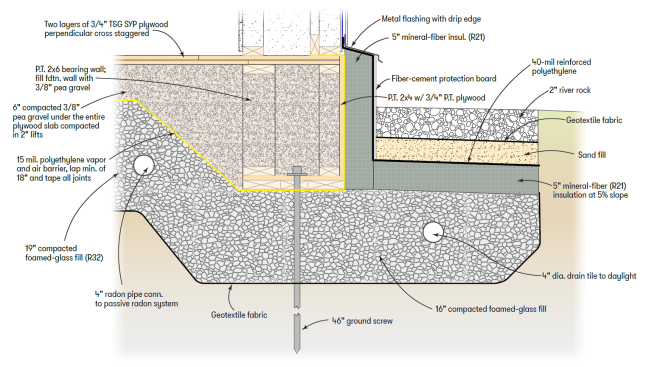
I took inspiration from other successful “slabless slabs” that eliminate the slab portion of the foundation. The examples I’ve seen, however, typically still rely on concrete for the footings and stem walls. In addition, many slabless slabs use either foam board (XPS or EPS) or mineral-fiber boards for sub-slab insulation. To eliminate the remaining concrete and the foam, and to minimize the amount of mineral-wool insulation, I incorporated ultra-lightweight foamed-glass aggregate (UL-FGA) and ideas from two rare but code-based systems. Permanent wood foundation systems gave me the idea of using pressure-treated wood as the structural element, and frost-protected shallow foundation design principles enabled that structural element to be shorter than normal. The result was a short (less than 2 feet tall) wood-footing-and-stem-wall system sitting on compacted foamed-glass aggregate that extends 2 feet around the foundation perimeter and prevents the soil below the wood footing from freezing. The side of the footing is insulated with exterior mineral fiber board. The insulation exposed above grade is finished with cement board and capped with a metal flashing.
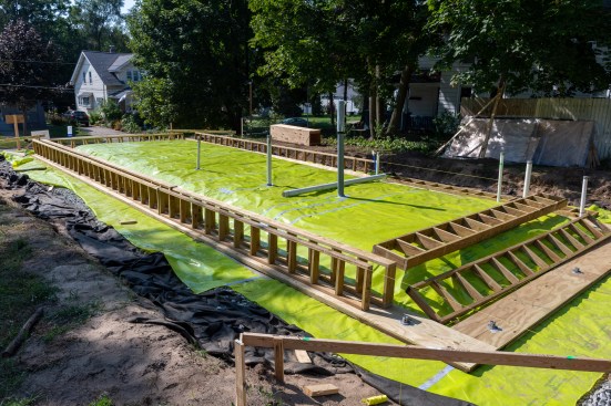
Site Prep
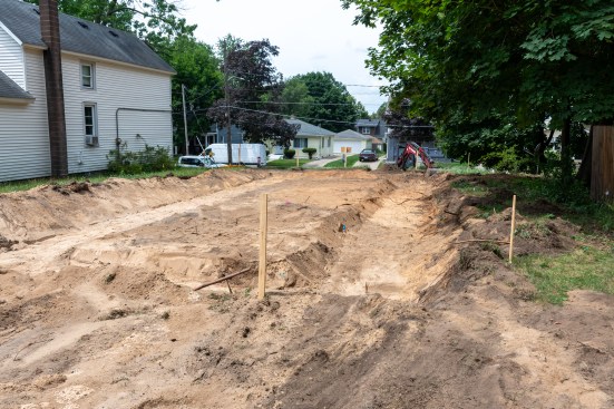
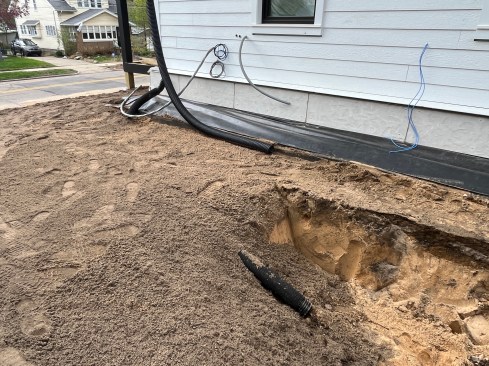
The excavation was shallow by Michigan standards. The excavator scraped off the topsoil and dug the perimeter about 2 ½ feet down for the frost protected shallow foundation. The soils on the site were sandy. I bored down about 7 feet with a hand corer and found clean, sugar sand all the way. It was beautiful material, but it didn’t have great bearing capacity. Fill sand, which is coarser and more angular, would have been better. Still, I calculated the weight on the footing along the long bearing walls at 1,082 pounds per square foot (psf), which was reduced to 624 psf when distributed through the UL-FGA on the geotextile. Per Terzaghi’s equation, the soil at excavation depth could handle 1,617 psf, so I had a workable safety margin, though I would have liked a bigger one.
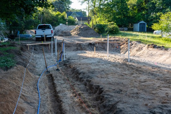
With the excavation roughed out, the plumbers roughed in the city drain and supply lines. Then, we covered the excavation with geotextile to stabilize the sandy soils and prevent the sand from working its way into the foamed-glass aggregate above it. Based on sieve analysis of the sand, I chose a heavy-duty (10 ounces/square foot), commercial-grade geotextile with a 100 U.S. sieve size. It was difficult to cut with a utility knife, so we bought heavy-duty scissors to cut it efficiently.
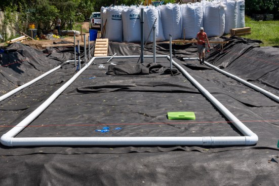
Final steps before placing the aggregate included placing 4-inch perforated drainpipe running to daylight to manage any groundwater and run-off that might seep under the house, placing 4-inch perforated pipe for passive radon venting, and setting temporary plywood edges in place to define the outside edge of the geotextile and foamed-glass aggregate.
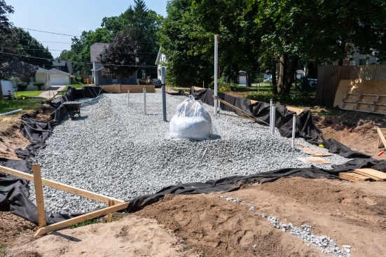
The initial excavation left the center area below the slab porti…
Foamed-Glass Aggregate
For the deep bed of foamed-glass aggregate (UL-FGA), we opted for AeroAggregates, largely because the company has a division closer to Michigan, so shipping (which has its own carbon impact) was half the price. AeroAggregates’ UL-FGA is a lightweight, closed-cell foamed-glass fill made from 100% recycled-glass containers. It has a high-friction surface, which helps the angular particles interlock when compacted, providing stability and a high compressive strength (approximately 2,500 psf for this material).
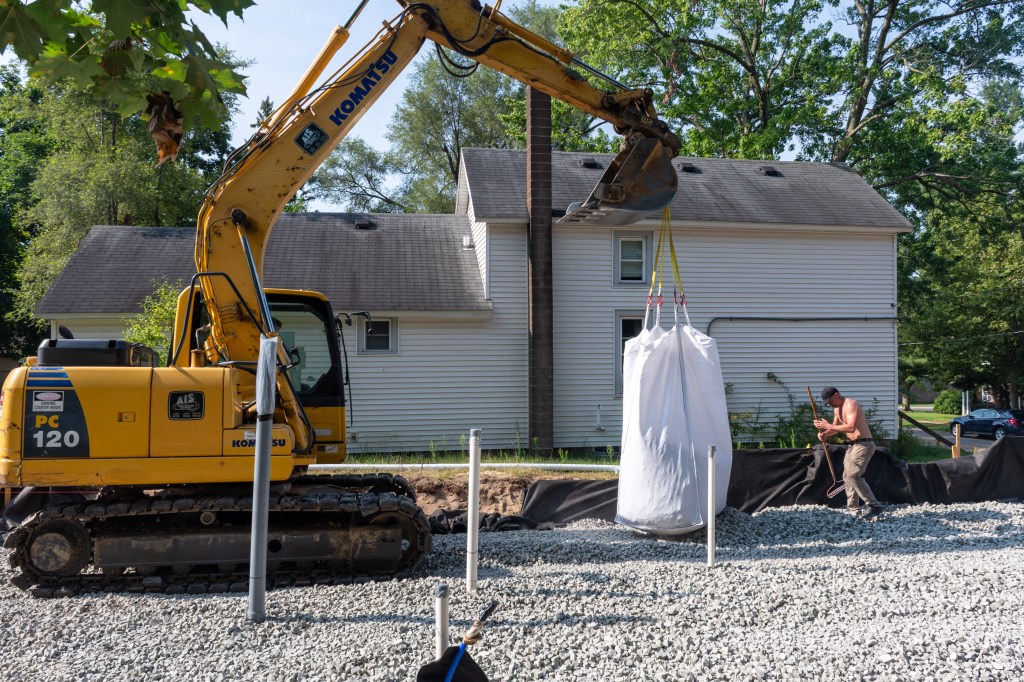
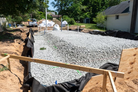
We placed about 16 inches of the fill in the footing area and 19 inches in the middle area under the slabless slab. Altogether, I ordered 105 yards of aggregate, delivered on a flatbed semi-truck in 3-yard super sacks. Unloading them was a lot of work. I climbed on the sacks, hooked a chain, and slung it over the bucket of the front-end loader, and we lifted each one.
To spread the fill, we got a little smarter and purchased a four-point sack lifter and brought in a small crane. We picked up each sack, swung it out over the area to be filled, cut the bottom open, and moved the opened sack around, working with shovels and spreaders to distribute the aggregate evenly, compacting as we went with a cordless Milwaukee MX Fuel plate compactor. Looking back, I should have had it delivered on a live-bottom truck and used a stone slinger to spread it. That would have saved a lot of work.
The coarse aggregate made it hard to achieve a smooth surface. I had ordered a finer grade but received only ½ yard, which was far too little. Next time, I’ll order several yards of the finer material to create a flat, even layer. That should make it easier to set the footings and achieve a level surface.
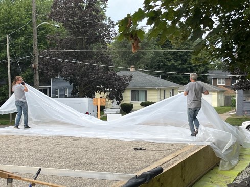
On top of the UL-FGA, we installed Stego’s 15-mil polyolefin vapor retarder. We taped the seams carefully, using a compatible tape (Compego), and repaired spots where tamping had torn holes. To protect the system from moisture, I bought a large, heavy-duty, scrim plastic sheet. We spent a lot of time covering and uncovering the foundation, then the framing as we went up, then the whole house before predicted storms. It kept things dry, but it was exhausting. Next time, we need to find a better strategy.
Wood Footings
Instead of pouring concrete footings, we built a footing system from kiln-dried after treatment (KDAT) lumber and plywood. I liked the kiln-dried material much better than typical PT lumber; it was lighter, truer, and less likely to warp. It also contained less moisture, which was important since I wanted minimal moisture in the system from the start.
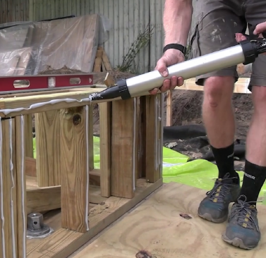
For a footing base, we formed a sled using treated 2x8s capped with treated plywood and anchored it to the earth with 46-inch aluminum ground screws. We framed the double stem walls from treated 2x4s and 2x6s sheathed with treated plywood. We glued all the framing together with Climate Non-Slump (NS) Adhesive, a moisture-curing polyether structural adhesive. This adhesive was designed primarily for bonding framing to sheathing to increase the resilience of wood-framed structures against extreme winds and seismic events. While this type of resilience was not strictly needed at the foundation level, the adhesive is a nontoxic, 100% solids formulation, and we used it extensively wherever construction adhesive would normally be applied. We even used it around the heads of the earth anchors to air seal the Stego penetrations. (We also used Climate NS Adhesive as it was intended, to secure the rest of the framing to help the structure withstand the extreme forces of straight-line winds, which have become increasingly common in our region.)
To monitor the system’s performance, I installed temperature and humidity sensors in the footing, walls, and roof. I can monitor these on my phone, and, so far, I haven’t seen relative humidity rise above 80% anywhere in the envelope system. Some areas are surprisingly dry, almost like desert microclimates. That reassures me that the system is working as intended.
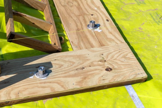
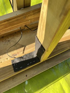

The double stem wall was built on a sled of treated 2x8s and tre…
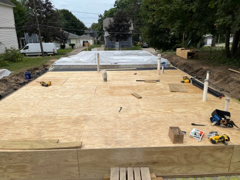
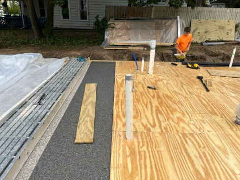
Pea Gravel and Plywood
Once the footing was in place, we filled the volume between the double stem walls with pea gravel and spread it to a minimum depth of 6 inches over the central slabless slab area, screeding it flat with a 2×4 aluminum tube across the top of the stem walls. This gravel would be covered with a double layer of ¾-inch T&G plywood. To prevent gravel from interfering with the tongue-and-groove, we laid fiberglass screen over it. That made laying the first layer of plywood easier and perhaps provided a little extra protection against insects. We glued the two layers of plywood together with Climate NS Adhesive.
We let some of the Stego vapor barrier stick out past the footing walls, thinking it might allow water to drain if it ever got in. In practice, it just got beat up and muddy. Next time, I would tape it up onto the footing walls and protect it from the start.
Frost and Moisture Protection
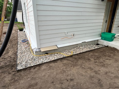
For our frost-protected design, we installed 5 inches of R21 mineral wool insulation (Powerwool 80, due to availability) on the vertical face of the foundation walls and extending 24 inches horizontally. Over this, we added a 40‑mil reinforced polyethylene pond liner to keep bulk water out of the insulation, and we protected this membrane with cement board secured to the sheathing with long stainless-steel screws. Finding ground-contact-rated cement board proved difficult. The only source I found, Finex, shipped from California, and shipping was expensive, not to mention the carbon intensity this added. Despite these setbacks, it seemed to be the best material for this application, and I felt the ground-contact-rating was critical.
On top of the pond liner, we placed a layer of fill sand and some geotex and then finished to grade with an 8-inch-thick-by-24-inch-wide layer of river rock to keep vegetation away from the house and to help manage water. On the south side, I directed the downspouts off the large roof plane (with a 12.5-kWp PV array) into a rain garden planted with native species, combining water management with ecological landscaping.
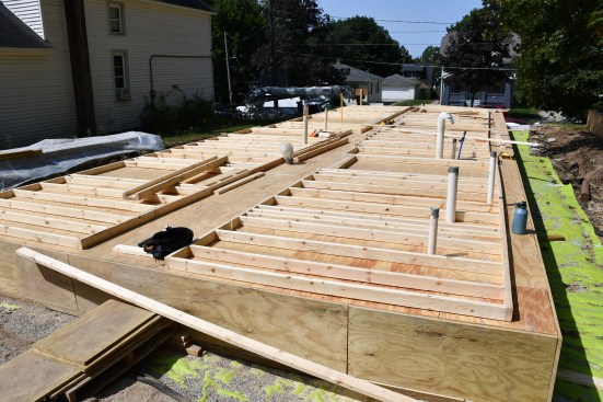
The crew sheathed over the foundation with two layers of 3/4-inc…
Reflections and Lessons Learned
Looking back, I would do many things differently next time. Most importantly, I would excavate the foundation area flat rather than leaving the elevated area beneath the slabless slab. This would require more pea stone (or perhaps a crushed stone next time), but the labor savings from not fighting the slope would make up for it. In addition, I would order more of the fine-grade UL-FGA to make it easier to screed and smooth the surface of the aggregate. I would button up the vapor barrier earlier, as mentioned, and I would build the wood footing walls more like space frame trusses, so they could more easily be set level, regardless of the site surface.
Nevertheless, I’m proud of what we accomplished. Building a foundation without concrete and foam insulation is an important advancement in sustainable residential design.
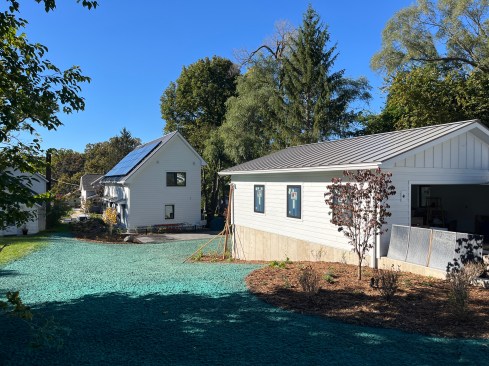
It’s also worth noting that the garage behind the house is on a steeper slope with a change in elevation of about 5 feet from the garage opening to the back nearest the house. This required pouring a 9-foot foundation wall to get below frost depth and support the backfill. I wasn’t comfortable going without concrete for this structure, so we built the garage foundation conventionally.
The comparison with the house foundation proved to be a nice proof of concept. The concrete work for the garage cost about $40,000, and we often had to wait for the concrete contractor. There were scheduling conflicts and time spent waiting for the formwork and footing pour, then the wall formwork and pour, then curing time before backfill and flatwork, and then more curing time before we could start framing. Being able to self-perform the foundation work for the house kept us moving without delays and proved to be an efficient way to build. This gives me confidence that, with the changes mentioned above, this is a viable, cost-effective method for future projects in addition to the significant (~60%) embodied carbon reductions we achieved in the house.