The evolution of high-performance homebuilding demonstrates an important truth that is not apparent to many homeowners: The building enclosure—not the mechanical system—does most of the work when it comes to making a home livable. With our first “MiNet0” house in Grand Rapids, Mich., I pushed this idea, building a 16½-inch-thick, double-stud enclosure that all but eliminates thermal bridging, shrugs off extended power outages, and allows the home to be heated and cooled with a single one-ton mini-split.
This home is the first certified Phius Zero house in the Grand Rapids area but it’s more than just super-efficient. It’s a case study in how a well-thought-out thermal envelope affects everything else. Besides only needing a small mechanical system, the house can support days, if not weeks, of livability during grid outages and is more resilient to wind and long-term wear.
The project also reflects how I think about carbon in residential construction. My goal wasn’t just to reduce operational energy, but to drive down the home’s carbon footprint across its entire life cycle. In this article, I explain how the enclosure made that possible and where the approach added complexity. And I offer some thoughts on how to cut carbon without sacrificing comfort, durability, or buildability.
I’ve written one article about this project that focused on the foundation system (“High-Performance Foundation without Concrete,” Jan/26); this one looks in detail at the rest of the home.
First Some Definitions
I refer to this home as offering resilience and comprehensive net zero performance. Since people understand those terms differently, I need to clarify how I define them.
By “resilience” I mean the house can operate normally during a grid-down event for one to two cloudy days and indefinitely on sunny days thanks to its large solar PV array. Even if all mechanical systems failed, the house is so well insulated and airtight that it could stay livable for several days and above freezing for at least a week during winter conditions. This is thanks in part to the home’s extra thermal mass. With 11 tons of TimberHP wood fiber insulation, ⁵/₈-inch drywall on the ceilings, and 50 tons of pea stone under the main floor slab, the house has a lot of thermal stability.
Virtual Tour
Click here for a virtual tour with clickable points for more information about this project.
By “comprehensive net zero,” I mean that, when designing this home, I took a broader view of net zero than simply “the house produces as much power as it uses on an annual basis.” My comprehensive approach also slashes the carbon footprint of the site more broadly. This home zeroes out the owner’s carbon footprint for their local transportation. Its PV panels can charge two EVs that are driven 33 miles/day each (assuming they can be driven 3 miles per kWh used). And we focus on reducing up-front, or embodied, carbon by 60% compared to conventional construction by eliminating concrete and foam, and by using wood-fiber insulation. We also chose low-carbon finishes like Dekton countertops, MILEstone Net Zero tile, hardwood floors, and site-harvested walnut for the window sills. My approach to building this home was also to make it more durable. I estimate that the materials we used will last roughly twice as long as the materials used in a typical home. For example, the standing-seam metal roof has a 60-year expected life vs. 30 years at best for asphalt. In addition, plywood was used rather than OSB throughout the project (¹/₂-inch CDX for sheathing, ¾-inch T&G SYP for subfloors, and ⁵/₈-inch CDX for the roof deck), and the Pro Clima membranes are tested for a 100-year life-span. The vented rain screen behind the siding and under the roof deck enables drying, further extending the life of the envelope. Because less material will need to be replaced over time and the house itself will last longer, the whole project’s life-cycle carbon footprint is reduced. The structure’s enhanced wind resistance also reduces repairs needed after high-wind events.
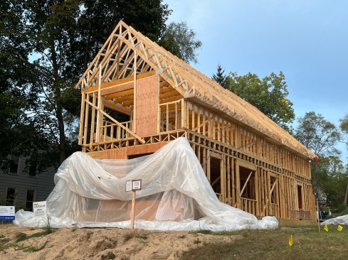
Double-Stud Complexity
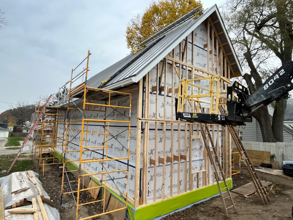
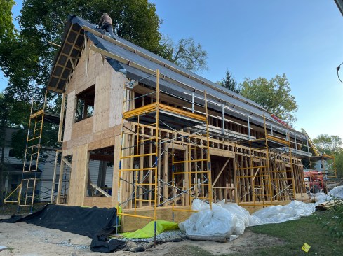
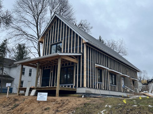
The house is narrow with a footprint measuring 20 feet wide by 52 feet long. The long walls face north and south, and the short walls east and west. We framed the walls using a double-stud system that consists of two 2×4 walls spaced 9 ½ inches apart for a total enclosure thickness of 16 ½ inches that achieves R59. This creates a deep cavity with very little thermal bridging but also introduces a lot of complexity and adds a good deal of time to the framing process. (More on that below.)
In his first project building a double-wall assembly, the author…
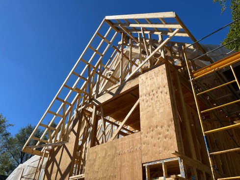
I based the wall design on 475 Building Supply’s Tier-3 double-wall assembly (475.supply/pages/double-stud), which aims to eliminate the structural sheathing (a high-risk condensing surface) and instead relies on diagonal strapping for shear resistance. However, we ran this by a structural engineer to ensure the house could handle the wind loads in our area. Here in West Michigan, we’ve seen an increase in straight-line winds, particularly during summer thunderstorms. These winds can exceed 60 to 80 mph and cause structural damage similar to what a tornado can bring. The engineer wasn’t comfortable relying on strapping alone and recommended we add plywood sheathing to the shorter east- and west-facing walls. Those walls have large window and door openings so to stiffen them we added ½-inch CDX plywood to the exterior face of the inner wall. In addition, we framed the front wall on the first floor as a portal frame.
To improve the wind resistance of the structure, we applied a ¹/₄-inch bead of Climate Non-Slump (NS) Adhesive (climateadhesive.com) between the sheathing and studs, between the double top plates, below the sole plate of the walls, and between the furring strips and the roof sheathing in our ventilated roof assembly. NS is a remarkable new structural adhesive that is 100% solids, has no VOCs, and is completely nontoxic for workers and occupants alike.
According to the manufacturer’s testing, this moisture-curing polyether acts as a shock absorber for light-frame wood, distributing the forces of violent wind and seismic events across the frame rather than concentrating those forces at metal fasteners. It’s relatively affordable—on par for cost with PL Premium—but is available in 20-ounce sausage packs. Most importantly, Climate Adhesive has managed to solve the embrittlement problem: the manufacturer claims that, unlike conventional construction adhesives, NS will not dry out, become stiff, or fracture, but will remain flexible over time.
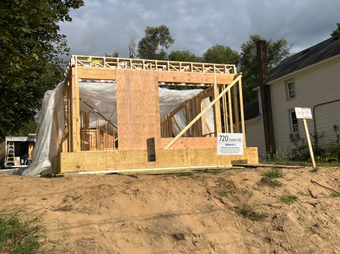
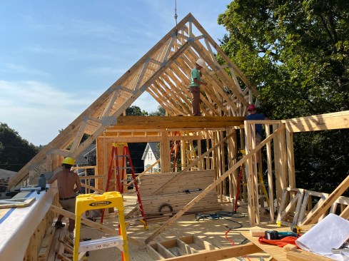
A Unique Roof Frame
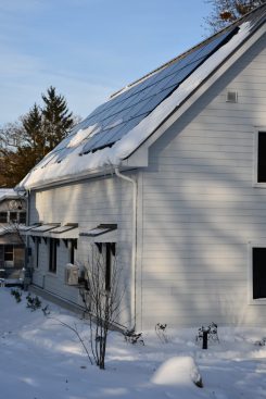
The need for solar power led us to design an asymmetrical gable roof. While each roof plane has the same pitch (12:12), the surface area of the south-facing roof is much larger and, as noted above, supports enough photovoltaic capacity (32 panels with a total peak output of 12.48 kWp DC) to power not just the house, but also two electric vehicles. The only exception would be during a grid-down event in extreme weather, when electric vehicles might need to be charged off site to preserve battery power to operate the home. In an extended grid-down event with little PV production, compatible EVs could charge elsewhere and deliver power to the house indefinitely.
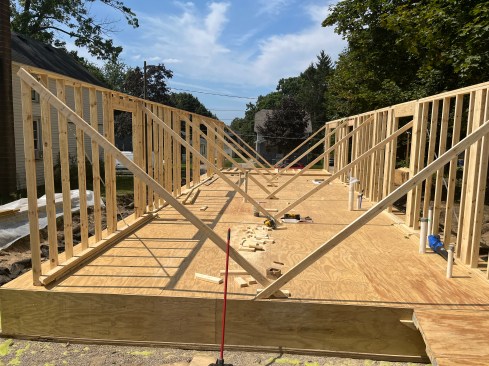
Designing the roof trusses and the attic frame were among the project’s biggest challenges. The trusses had to bear on a 16 ½-inch-wide wall, which isn’t something truss manufacturers see every day. There was a lot of back-and-forth. The initial design was not configured as a parallel-chord truss, but we needed the continuous depth for the roof insulation (resulting in a conditioned attic). Also, we needed to include the floor structure for the attic, but with only one side of that floor bearing directly on an exterior wall the forces were a bit tricky for the designer.
In the end, we did manage to arrive at a workable design. The roof trusses have parallel chords spaced 25 inches apart, which left plenty of room for dense-packed wood-fiber insulation that achieves R93. For the span across the second-floor ceiling, we had the truss built with 9 ¼-inch LVLs. One end of each LVL is supported by the bottom chord of the truss mid-span on the south-facing side, while the opposite end bears on the north-facing exterior wall. I also specified blocking trusses—small rectangular truss frames —which we installed between the tall truss heels above the inner (bearing) 2×4 walls. They provide a more secure connection to the top plate, helped keep the truss stable while we set them (making for a safer, easier process), and provide additional wind shear resistance to the (more or less) sheathing-less design.
We completed the roof and dried-in the house before building the outer double wall, which meant there was no wall to support the last rafters of the rake overhang. To manage that, we added diagonal 2×4 bracing on the gable ends. These braces would later end up inside the wall assembly once the outer wall was framed.
Details to Keep Framing Cavities Dry
Super-insulated building assemblies have the potential for big moisture problems because all that insulation in the extra-deep wall and roof cavities reduces heat flow, which in turn slows drying. We solved part of the problem by leaving off the exterior sheathing, which eliminated a potentially high-risk condensing surface—a vulnerability for many fat-wall assemblies (“Major Surgery for a Failing Fat Wall,” 11/15). However, even without this condensing surface, the reduced drying potential of the assembly meant we had to take steps to ensure the insulation stayed dry. We would need to keep humid air from inside and outside the home out of the wall cavity and prevent wind-driven rain and snow from penetrating the eaves and siding.
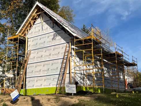
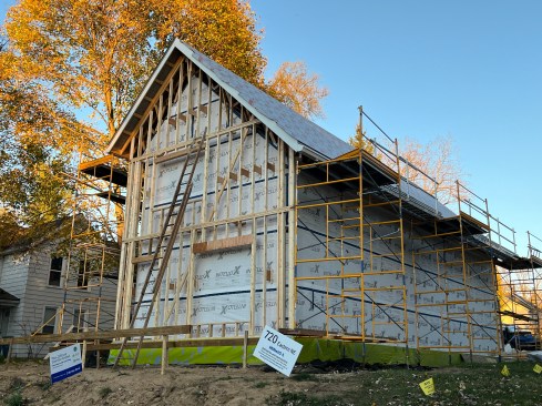
Solitex Mento—a vapor open weather barrier—covers the roof t…
For air and vapor control, we leaned heavily on vapor-open and vapor-variable membranes. Namely, we installed Pro Clima’s Intello X—a vapor-variable membrane available from 475 Building Supply—on the underside of the roof trusses and on the outside surface of the 2×4 inner wall. It’s an upgraded version of Pro Clima’s Intello product that offers enhanced durability in extreme weather conditions.
As the air barrier, Intello X’s primary job is to block airflow created by pressure differences between the indoors and outdoors (caused by wind pushing or pulling on the envelope or from mechanical pressure generated indoors). As a vapor-variable membrane, it also keeps indoor humidity inside the house in the winter, and outdoor humidity outside in the summer. Only if or when relative humidity (RH) rises to 80% does it open up to allow humidity through it. (Vapor diffusion resistance decreases as RH increases.) In the summer, if RH in the wall rose to 80%, it would allow the wall to dry into the mechanically cooled and dehumidified interior of the house.
We installed Solitex Mento Plus from 475 Building Supply on the exterior of the trusses and over the outer wall of the double-stud assembly. This product serves as an air block to prevent wind from blowing through the insulation. It also functions as a weather-resistive barrier, helping to keep the walls and roof dry by serving as a drainage plane for our vented rainscreen behind the siding and under the roofing.
We put a lot of time into sealing wall-to-foundation, membrane-to-membrane, and wall-to-roof transitions, relying on careful taping with Tescon Vana tape (also from 475 Building Supply). We also used liberal amounts of Contega HF sealant on difficult membrane connections and Climate NS Adhesive on framing and plywood joints. The Intello X transitions from the walls to the underside of the trusses were particularly tricky, as was working up through the attic floor on the underside of the trusses.
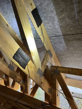
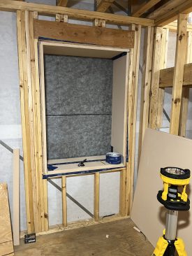
Note the details at the top of Photo 13 where the Intello is cut into flaps and taped, sealed, and reinforced with 2×2 blocking to withstand dense-packed insulation pressure. Also note that the 2x2s under the Intello create a service cavity for wiring and protect the membrane over the life of the house.
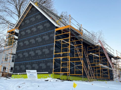
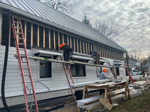
On the roof, we created a ventilated roof assembly by installing 2×2 furring strips over the Mento Plus membrane and then placing ⁵/₈-inch plywood sheathing on top of that. The ventilated cavity improves drying potential and therefore durability. A specialist roofing contractor installed the double-hemmed standing-seam metal roof over a heavy, continuous, stick-on underlayment applied over the plywood. The steep 12/12 slope made installation challenging, but improves winter PV performance by facing the winter sun more squarely and improving the ability for snow to slide off. The goal was to get closer to meeting the high winter electrical needs due to the heating load on the heat pump.
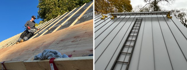
Over the Mento Plus on the roof, the crew installed 2×2 battens and ⁵/₈-inch plywood to create a ventilated roof before installing standing-seam metal roofing.
Snow management was another consideration. On the south side, I set the eavestrough (or gutter) low enough so snow can slide right over it and into the rain garden below. On the north side, we used snowguard rails to prevent slide-offs from falling onto the walking path there.
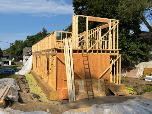
Once the roof was done, we built the outer wall. The interior and exterior walls are connected only by small plywood gussets, placed wherever there wasn’t a plywood window or door buck. When everything is open, you can literally see all the way down the wall cavity from one end of the house to the other.
The open cavity minimizes thermal bridging, but it also made construction more labor-intensive than I expected. I initially thought, “How hard can it be to build two walls?” In practice, it was more than double the work. There was a lot of fussing—straightening studs, aligning planes, and sometimes taking things apart and redoing them.
Insulation and Windows
Dense-pack TimberHP wood-fiber insulation (timberhp.com) fills the main wall and roof cavities. TimberHP batts were used in the interior 2×4 wall frames, which also function as service cavities for electrical and plumbing. The dense-pack installation turned into a major learning curve (for more on the challenges of blowing wood-fiber insulation (“On Site with TimberHP,” 5/25). Our installers had never worked with wood-fiber insulation before, and the large, open cavities made it difficult to achieve proper density. They were on site for weeks, and I’m not sure they made any money on the job, but in the end, we got it filled correctly.

Over 11 tons of wood-fiber insulation was blown into the double-wall assembly. On the underside of the trusses, the Intello needed to be cut into flaps, taped, and then reinforced with 2×2 blocking to withstand the pressure of dense-packing the insulation.
The windows are quad-pane Alpen windows (thinkalpen.com). I started with triple-pane in my WUFI energy model, but the U-value wasn’t low enough to meet the annual heating demand target so quad-pane became necessary. The windows are Phius-certified.
Around the windows, over the plywood bucks, we used a structural polyurethane foam board from Thermal Bridging Solutions (thermalbridgingsolutions.com), layering it to over-insulate the frames. While it performed well thermally, I did fire testing with a propane torch and didn’t like how it behaved. It produced a lot of black smoke and continued burning after the flame was removed, so it’s not a product I plan to use again. (Next time, I’ll look into BOSIG; bosig.de/en.)
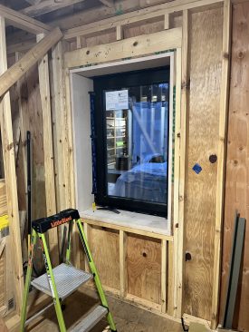
Structural foam board from Thermal Bridging Solutions insulates …
HVAC: Small by Design
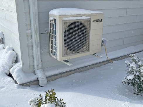
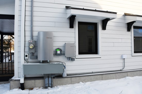
With our dual-membrane wall system, triple-gasketed, Phius-certified, quad- pane windows, and attention to detail, we obtained 0.0285 CFM50 of air leakage—less than half of the Phius requirement of 0.06 CFM50. With 5,546 square feet of envelope and 15,786 cubic feet of volume, we achieved 0.60 ACH50. Because the envelope is so robust, the mechanical systems are intentionally small. The house is heated and cooled with a one-ton Mitsubishi mini-split. Domestic hot water is provided by a SanCO₂ heat- pump water heater, which I chose so I wouldn’t be adding a space-heating load during winter.
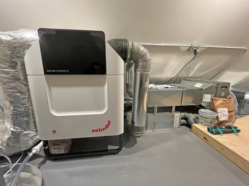
Ventilation is handled by a Zehnder ERV, distributing air through multiple 3-inch supply and extract tubes. We insulated both the intake and exhaust heavily to avoid condensation and heat loss, especially since those pipes are in conditioned space.
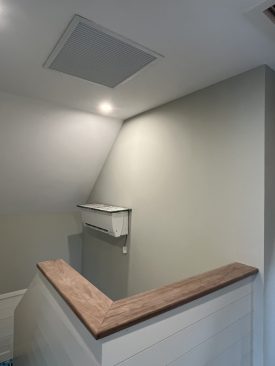
One assumption that didn’t hold up was that the ERV would distribute the mini-split heat through the house. In practice, this didn’t work at all. I ended up with a serious temperature stratification problem—so serious that the inspector noticed it immediately and wouldn’t approve the system.
To fix it, I added three Ruck inline fans (made by Ruck Air Movement out of Germany; I sourced them through HVACQuick.com) that pull air from a stairwell plenum and distribute it to the living spaces. Each fan has a speed control, which allows some adjustment room by room. It works very well in heating mode—I’m seeing only less than a two-degree difference between floors—but I haven’t yet proven how it will perform during the cooling season.
This was not how I would design the system from scratch next time. It was a fix, not an ideal solution, and I’m still unsure how homeowners will perceive it. Some may appreciate the control; others may find it complicated. Next time, I will design a zoned mini-split system to avoid the stratification issue.
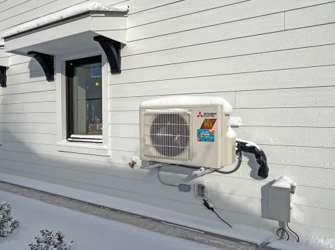

A single one-ton Mitsubishi mini-split is sufficient to heat and…
Actual Performance
We had an extreme test of the heating performance on some sub-zero days in January. The one-ton heat pump was designed to maintain a 65-degree F setpoint down to 5 degrees F ambient. It did so until 0 degrees F with no occupants or activity in the house over a weekend, but slipped a few degrees when the temperature plunged to -10 degrees F. When occupied, we expect that this home will maintain setpoint even below zero due to heat generated by occupants, lights, and appliances. Summer cooling performance is easier; the one-ton heat pump has double the capacity needed to meet the calculated load on a design cooling day. The only question that remains is how well our Ruck circulating fans will move cool air around the house next summer.
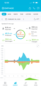
The PV array performance has been good; Snow slides off much sooner than it does on the east/west facing arrays on my own home’s 8/12 shingled roof. After some cloudy, snow-covered, zero-performance days in January, the sunnier days in February have produced the power needed to run the house. We anticipate that the array will overproduce consistently in the April through September months. With the underproduction in dreary December and January months, we expect the owner to be operationally net zero on balance, with a small residual bill (because in Michigan, we sell extra power to the utility at half price in the summer and buy at full price in winter).
Enhanced Envelope
If there’s one clear takeaway from this project, it’s that the building envelope enables everything else. The level of performance in the walls and roof allowed me to use very small mechanical systems and create a very comfortable house free of any cold spots or condensation. At the same time, every decision—framing, air-sealing, insulation, and mechanical layout—had more implications than I initially expected. The next one will be easier!